Specifications
Part Numbers
| Frequency (MHz) |
Element Diameter |
Focus |
Part Number |
| inch |
mm |
GP* |
HR* |
C* |
Accessories |
| 2.25 |
0.25 |
6.4 |
None |
00-011300 NF |
00-011301 NF |
00-011302 NF |
|
| Spherical |
00-011300 X.XS |
00-011301 X.XS |
00-011302 X.XS |
|
| Cylindrical |
00-011300 Y.YC |
00-011301 Y.YC |
00-011302 Y.YC |
|
| 5 |
0.25 |
6.4 |
None |
00-011303 NF |
00-010593 NF |
00-010711 NF |
|
| Spherical |
00-011303 X.XS |
00-010593 X.XS |
00-010711 X.XS |
Cable |
| Cylindrical |
00-011303 Y.YC |
00-010593 Y.YC |
00-010711 Y.YC |
MD – BNC |
| 10 |
0.25 |
6.4 |
None |
00-010822 NF |
00-010377 NF |
00-010823 NF |
6-ft (1.83 m) |
| Spherical |
00-010822 X.XS |
00-010377 X.XS |
00-010823 X.XS |
07-010012 |
| Cylindrical |
00-010822 Y.YC |
00-010377 Y.YC |
00-010823 Y.YC |
|
| 15 |
0.25 |
6.4 |
None |
|
00-010596 NF |
00-011304 NF |
|
| Spherical |
|
00-010596 X.XS |
00-011304 X.XS |
|
| Cylindrical |
|
00-010596 Y.YC |
00-011304 Y.YC |
|
Please choose your part number based on case type, transducer frequency, and element diameter. To specify the focal length (in inches) and focal type (spherical or cylindrical) you desire: Edit the X.XS and Y.YC suffixes shown in the chart to match your requirements. See Focal Length and Type for more information. *See Technology & Features for more information on transducer series.
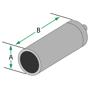
Case Dimensions
| Element Diameter |
A |
B |
| inch |
mm |
| 0.25 |
6.4 |
0.38 in. |
9.7 mm |
1.25 in. |
31.8 mm |
Focal Length / Type
To specify the Focal Length (in inches) and Focal Type (spherical or cylindrical) you desire: Edit the X.XS and Y.YC suffixes shown in the chart to match your requirements. (ex. The suffix for a 2.0″ spherical focus is changed from X.XS to 2.0S; the suffix for a 3.0″ cylindrical focus is changed from Y.YC to 3.0C)
NF = Non-focused (flat); S = Spherical focus; C = Cylindrical focus
| Frequency (MHz) |
|
Element Ø (Inches) |
| 1 |
0.75 |
0.5 |
0.375 |
0.25 |
| 1 |
Near |
4.3 |
2.4 |
1.1 |
|
|
| Min |
2 |
1.5 |
0.75 (2) |
|
|
| Max |
2.75 |
1.75 |
0.75 (2) |
|
|
| 2.25 |
Near |
9.6 |
5.4 |
2.4 |
1.4 |
0.6 |
| Min |
2 |
1.5 |
1 |
0.75 |
0.375 (2, 3) |
| Max |
6 |
3.5 |
1.5 |
1 |
0.375 (2, 3) |
| 3.5 |
Near |
15 |
8.4 |
3.7 |
2.1 |
0.9 |
| Min |
2 |
1.5 |
1 |
0.75 |
0.375 (3) |
| Max |
8 |
5.5 |
2.25 |
1.25 |
0.5 |
| 5 |
Near |
21 |
12 |
5.4 |
3 |
1.3 |
| Min |
2 |
1.5 |
1 |
0.75 |
0.5 |
| Max |
8.0 (1) |
7.5 |
3.5 |
2 |
0.75 |
| 10 |
Near |
|
24 |
10.7 |
6 |
2.7 |
| Min |
|
1.5 |
1 |
0.75 |
0.5 |
| Max |
|
8.0 (1) |
6 |
4 |
1.5 |
| 15 |
Near |
|
|
16 |
9 |
4 |
| Min |
|
|
1 |
0.75 |
0.5 |
| Max |
|
|
6.0 (1) |
5 |
2 |
Near = Nearfield length in water; Min = Minimum recommended focal length in water; Max = Maximum recommended focal length in water
All focal lengths are listed in inches of water from the reflection off a flat stainless steel reflector. Divide by 4 for the approximate distance in steel.
Focal lengths are offered in 0.35″ increments between the Min. and Max listed. Focal lengths outside the recommended limits can be ordered, but on a best effort bases only.
1 – Achievable focal lengths of these models are shorter compared to their near field length due to attenuation and other effects at long water paths. Longer focal lengths can be ordered, but on a best effort basis.
2 – Max and Min. focal lengths are the same for these models due to the physics and geometry of this combination.
3- A focal length other than the normal 0.25″ increment is offered in this combination.
Please confirm your focal length in your applications: Use of probes with F-Numbers under 4.0 (near the minimum focal length listed on this chart) can introduce other wave modes and/or be less effective since acoustic energy at the edge of the beam may be at relatively high incident angles. F-Number = Focal Length/Element Diameter. (ex. 2.0″ focus probe with 0.375″ element = 2.0″/0.375″ = F-Number = 5.3)

